How do substations work on the electricity grid?
Electricity doesn’t flow directly from power stations to homes and businesses. Instead, it moves through a network of substations that step voltage up and down, route power across the grid, and help keep the system stable in real time.
Without substations, the electricity network simply wouldn’t function. This guide explains the essential role of electrical substations in Britain. Here’s what we cover:
- What is an electrical substation?
- Why substations are necessary on the national grid
- How electrical substations work
- What equipment is found inside a substation?
What is an electrical substation?
An electrical substation is a key part of the power network that transforms, controls, and distributes electricity as it moves from generators to homes and businesses.
Its primary role is to convert electricity from one voltage level to another, enabling efficient long distance transmission and safe delivery through local distribution networks.
Substations also contain switching and protection equipment that helps to route power, isolate faults, and keep the electricity system operating reliably.
Why substations are necessary on the national grid
This section explains the three essential functions of substations on the British electrical grid.
Stepping down the voltage
Electricity is transmitted more efficiently over long distances at very high voltages because this reduces the current required, minimising resistive heating losses in overhead lines.
The nationwide transmission network uses high-voltage lines supported by tall pylons to transmit electricity across the country with minimal losses.
At the regional distribution level, this high-voltage infrastructure is impractical, so progressively lower-voltage levels are used as the network becomes more localised.
Here is the typical structure of voltage levels used in the British grid:
| Network level | Typical voltage |
|---|---|
| Nationwide transmission network | 400 kV / 275 kV |
| Sub-transmission | 132 kV |
| Regional distribution | 33 kV |
| Local distribution | 11 kV |
| Three-phase supply to energy-intensive commercial buildings | 400 V |
| Final supply to homes/other commercial properties | 230 V |
Substations sit between each of these stages and transform electricity from one voltage level to another, ensuring the power is suitable for the next part of the network.
The final stages of voltage stepping down take place at a local level, where voltages are reduced to 400 V/230 V, the standard voltages used in domestic and business electricity connections.
Routing of electricity across the grid
Substations on the electricity grid serve as junctions where multiple lines meet.
A substation allows electricity to be:
- Redirected to different transmission lines
- Sent into different distribution feeders
- Routed around faults or maintenance work
Substations can be remotely operated by central control centres that monitor electricity flows and reconfigure the network when required.
Protecting equipment and maintaining system stability
Electrical faults can occur on the grid due to lightning strikes, damaged equipment, or equipment failures.
Substations contain protection systems and circuit breakers that automatically detect these faults and disconnect the affected part of the network.
This helps prevent damage to network equipment and supports the stability of the wider electricity system.
How electrical substations work
The diagram below shows the key processes and components of a typical electrical substation on the British National Grid.
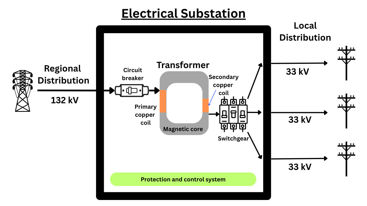
This section explains the function of each component and how they operate.
Circuit breakers
A circuit breaker in a substation is a specialised high-voltage switch designed to interrupt the flow of electricity instantly when a fault occurs.
Unlike a normal switch, it can safely break the extremely large currents used by the grid without damaging equipment or destabilising the power network.
Within the circuit breaker, the electrical connection is physically separated. To prevent electricity from flowing across the air gap and causing overheating, high-pressure sulphur hexafluoride (SF₆) gas is used to extinguish the arc at the point of disconnection.
For simplicity, the diagram above shows the circuit breaker installed before the transformer. In reality, individual circuit breakers are also installed at each outgoing connection to the local distribution network, allowing downstream connections to be isolated individually.
Circuit breakers can be triggered automatically by the protection and control system or manually by engineers or grid operators.
Transformer
The transformer is the part of the substation that changes electrical voltage from one level to another. In the example above, the transformer reduces the voltage from 132 kV used for regional distribution down to 33 kV used in local distribution.
A transformer consists of two sets of copper coils wrapped around a magnetic core. Here’s how it works:
- Alternating current (AC) from the incoming connection flows through the primary winding, creating a changing magnetic field in the core.
- This changing magnetic field induces a voltage in the secondary winding.
This process transfers electrical energy between the two circuits without directly connecting the coils.
The output voltage depends on the turns ratio between the primary and secondary windings. If there are fewer turns in the secondary winding, as in the example above, the voltage will be stepped down.
The number of turns in the copper coils is configured to produce the required voltage at the substation’s outgoing connections.
Switchgear
Switchgear in an electrical substation allows the transformed power to be distributed to multiple outgoing lines.
The switchgear serves as a controlled junction point for high-voltage electrical power. In the example, these are the individual 33 kV lines that distribute power to nearby towns or villages.
Switchgear enables the Distribution Network Operator to remotely control the distribution of electricity from the substation.
What equipment is found inside a substation?
The following table provides a comprehensive list of equipment typically found in British electrical substations, along with a brief explanation of each item’s purpose.
| Equipment | Function |
|---|---|
| Transformer | Changes electricity from one voltage level to another. |
| Circuit breaker | Automatically or manually disconnects a circuit during a fault or switching operation. |
| Switchgear | Controls, protects, and isolates circuits within the substation. |
| Busbar | Acts as a common connection point that distributes power between multiple circuits. |
| Isolator / disconnector | Provides a visible off-load isolation point so equipment can be worked on safely. |
| Protection relays | Detect faults and send trip signals to circuit breakers. |
| Current transformers (CTs) | Reduce high current to a measurable level for protection and metering. |
| Voltage transformers (VTs) | Reduce high voltage to a measurable level for protection and metering. |
| Surge arresters | Protect equipment from transient overvoltages such as lightning or switching surges. |
| Earthing system | Safely dissipates fault current into the ground and helps protect people and equipment. |
| Insulators | Support live conductors while preventing unwanted current flow to earth. |
| Capacitor banks / reactors | Help control voltage and manage reactive power on the network. |
| Protection and control panels | House the relays, controls, and automation used to operate the substation. |
| Remote monitoring system | Allows operators to monitor alarms, status, and switching remotely. |
Differences between transmission substations and distribution substations
In Britain, the national grid is divided into two parts:
- A nationwide transmission network that forms the backbone of the grid and primarily operates at 400 kV and 275 kV.
- Regional distribution networks that connect to homes and businesses. These connect to the transmission network and step down voltage through 132 kV, 33 kV, 11 kV, and finally 230/400 V.
Substations are installed at each point where the grid steps down the voltage.
The technology used in substations across transmission and distribution networks is broadly similar; however, substation size varies significantly with voltage level.
Substations become larger at higher voltages because the equipment requires more insulation and greater physical separation to prevent electrical arcing between components. High-voltage transformers, busbars, insulators, and circuit breakers are therefore larger and spaced farther apart, which increases the site’s overall size.
Transmission substations can be very large. For example, a new substation planned for the transmission network in South Wales is expected to be roughly the size of 13 football pitches.
At the other end of the scale, an 11 kV to 230 V substation is typically the size of a small shed and is often found in housing estates or supermarket car parks.
Why are substations located near towns and cities?
Substations are located near towns and cities because electricity demand is concentrated there.
The general purpose of the grid is to distribute power from UK wind farms, gas power stations, and nuclear power stations to end users.
Over long distances between towns and cities, electricity is most efficiently transmitted at high voltages. As these high-voltage lines approach a population centre, the voltage must be stepped down by substations to levels suitable for consumers.
Electrical substations – FAQs
Our energy experts answer frequently asked questions about electrical substations used on the national grid.
Are electrical substations dangerous?
Electrical substations are not dangerous to the public when they are properly designed and secured.
They are built with extensive safety systems, including fencing, insulation, earthing, and automatic protection equipment, to prevent accidental contact and manage faults safely.
However, they contain high-voltage equipment and can be extremely dangerous if entered or interfered with, which is why access is restricted to trained engineers.
Who operates electrical substations?
Substations are usually operated by the network company that owns that part of the grid:
- Transmission network operators: National Grid Electricity Transmission in England and Wales, Scottish Hydro Electric Transmission in the north of Scotland, and SP Energy Networks in central and southern Scotland.
- Distribution network operators: Regional licensed operators.
- Independent distribution network operators: Private licensed companies operating small-scale extensions to DNO networks.
NESO coordinates the activities of these network operators in its role of maintaining balance across the British electricity system.
Who pays to maintain electrical substations?
Network operators pay the operating and maintenance costs of electrical substations.
These operators recover their costs through the following network charges, which are paid by domestic and business energy suppliers:
- TNUoS charges: Regulated fees recovered by transmission network operators.
- DUoS charges: Regulated fees recovered by distribution network operators.
These charges are set annually by the regulator Ofgem. Energy suppliers pass these costs on through domestic and business electricity prices.
- Share: